


 定义工作名和工作标题。
 定义工作文件名:依次选择Utility Menu→File→Change Jobname,会出现“Change Jobname”对话框,在对话框中输入工作文件名“Compressible Flow”,并将“NEW log and error files?”设置为“Yes”,如图6-3所示,单击“OK”按钮关闭对话框。
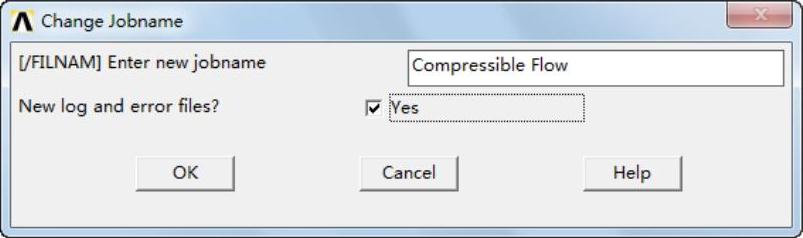
图6-3 “Change Jobname”对话框
 定义工作标题:依次选择Utility Menu→File→Change Title,会出现“Change Title”对话框,在对话框中输入工作标题“Compressible Flowin a Converging Diverging”,如图6-4所示,单击“OK”按钮关闭对话框。
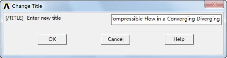
图6-4 “Change Title”对话框
 设置参数:依次选择Main Menu→Preferences,会出现“Preferences for GUI Filtering”对话框,选择“FLOTRAN CFD”,如图6-5所示,单击“OK”按钮关闭该对话框。
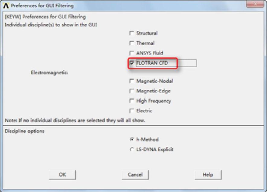
图6-5 “Preferences for GUI Filtering”对话框
 定义单元类型。
 指定单元类型:依次选择Main Menu→Preprocessor→Element Type→Add/Edit/Delete,会弹出“Element Types”对话框,如图6-6所示。
 单击“Add”按钮,会弹出“Library of Element Types”对话框。
 在“Library of Element Types”列表框中选择“FLOTRAN CFD”和“2D FLOTRAN141”,在“Element type reference number”输入框中输入1,如图6-7所示。单击“OK”按钮关闭“Library of Element Types”对话框。

图6-6 “Element Types”对话框
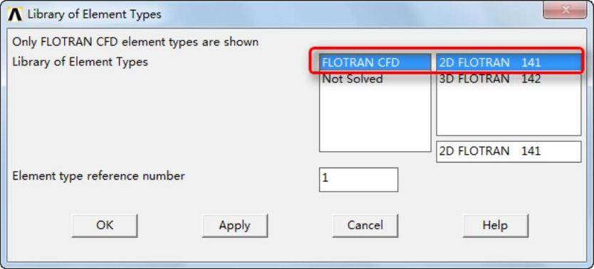
图6-7 “Library of Element Types”对话框
 单击“Close”按钮,关闭“ElementTypes”对话框。
 建立几何模型。
 依次选择Main Menu→Preprocessor→Modeling→Create→Keypoints→In Active CS,会弹出“Create Keypoints in Active Coordinate System”对话框,如图6-8所示,在“Keypoint number(NPT)”输入框中输入1,在“Location in active CS(XandY)”输入框中分别输入0和2.432。
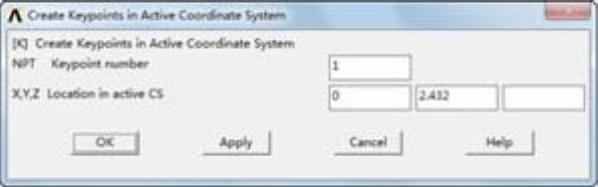
图6-8 “Create Keypoints in Active Coordinate System”对话框
 单击“Apply”按钮会再次弹出“Create Keypoints in Active Coordinate System”对话框,在“Keypoint number(NPT)”输入框中输入2,在“Location in active CS(XandY)”输入框中分别输入0和0。
 单击“Apply”按钮会再次弹出“Create Keypoints in Active Coordinate System”对话框,在“Keypoint number(NPT)”输入框中输入3,在“Location in active CS(XandY)”输入框中分别输入1和2.432。
 单击“Apply”按钮会再次弹出“Create Keypoints in Active Coordinate System”对话框,在“Keypoint number(NPT)”输入框中输入4,在“Location in activ eCS(XandY)”输入框中分别输入1和0。
 单击“Apply”按钮会再次弹出“Create Keypoints in Active Coordinate System”对话框,在“Keypoint number(NPT)”输入框中输入5,在“Location in active CS(XandY)”输入框中分别输入2和2.232。
 单击“Apply”按钮会再次弹出“Create Keypoints in Active Coordinate System”对话框,在“Keypoint number(NPT)”输入框中输入6,在“Location in active CS(XandY)”输入框中分别输入2和0。
 单击“Apply”按钮会再次弹出“Create Keypoints in Active Coordinate System”对话框,在“Keypoint number(NPT)”输入框中输入7,在“Location in active CS(XandY)”输入框中分别输入5和0。
 单击“Apply”按钮会再次弹出“Create Keypoints in Active Coordinate System”对话框,在“Keypoint number(NPT)”输入框中输入8,在“LocationinactiveCS(XandY)”输入框中分别输入5和0.7。
 单击“Apply”按钮会再次弹出“Create Keypoints in Active Coordinate System”对话框,在“Keypoint number(NPT)”输入框中输入9,在“Location in active CS(XandY)”输入框中分别输入6和0。
 单击“Apply”按钮会再次弹出“Create Keypoints in Active Coordinate System”对话框,在“Keypoint number(NPT)”输入框中输入10,在“Location in active CS(XandY)”输入框中分别输入6和0.5。
 单击“Apply”按钮会再次弹出“Create Keypoints in Active Coordinate System”对话框,在“Keypointn umber(NPT)”输入框中输入11,在“Location in active CS(XandY)”输入框中分别输入14和0。
 单击“Apply”按钮会再次弹出“Create Keypoints in Active Coordinate System”对话框,在“Keypoint number(NPT)”输入框中输入12,在“Location in active CS(XandY)”输入框中分别输入14和0.8,单击“OK”按钮关闭该对话框。
 依次选择Utility Menu→PlotCtrls→Numbering,会弹出“Plot Numbering Controls”对话框,如图6-9所示,单击“LINELine numbers”后的方框,使off状态变为on,单击“OK”按钮关闭该对话框。
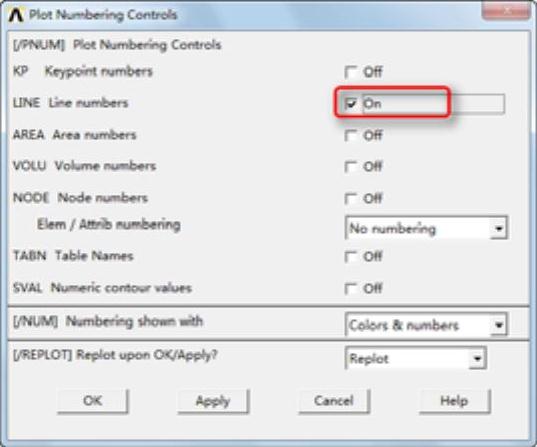
图6-9 “Plot Numbering Controls”对话框
 依次选择Main Menu→Preprocessor→Modeling→Create→Lines→Lines→In Active Coord,会弹出“The Lines in Active Coord”对话框,用鼠标依次选取关键点2和4。
 单击“Apply”按钮,会再次弹出“The Lines in Active Coord”对话框,用鼠标依次选取关键点3和4。
 单击“Apply”按钮,会再次弹出“The Lines in Active Coord”对话框,用鼠标依次选取关键点1和3。
 单击“Apply”按钮,会再次弹出“The Lines in Active Coord”对话框,用鼠标依次选取关键点1和2。
 单击“Apply”按钮,会再次弹出“The Lines in Active Coord”对话框,用鼠标依次选取关键点5和8,单击“OK”按钮关闭该对话框。
 依次选择Main Menu→Preprocessor→Modeling→Create→Lines→Lines→Tan to 2 Lines,会弹出“Line Tangent to 2 Lines”对话框,用鼠标选取线段3。
 单击“Apply”按钮,会再次弹出“Line Tangent to 2 Lines”对话框,用鼠标拾取关键点3。
 单击“Apply”按钮,会再次弹出“Line Tangent to 2 Lines”对话框,用鼠标拾取线段5。
 单击“Apply”按钮,会再次弹出“Line Tangent to 2 Lines”对话框,用鼠标拾取关键点5,单击“OK”按钮关闭该对话框。
 依次选择Main Menu→Preprocessor→Modeling→Create→Lines→Lines→In Active Coord,会弹出“The Lines in Active Coord”对话框,用鼠标依次选取关键点10和12,单击“OK”按钮关闭该对话框。
 依次选择Main Menu→Preprocessor→Modeling→Create→Lines→Lines→Tan to 2 Lines,会弹出“Line Tangent to 2 Lines”对话框,用鼠标选取线段5。
 单击“Apply”按钮,会再次弹出“Line Tangent to 2 Lines”对话框,用鼠标拾取关键点8。
 单击“Apply”按钮,会再次弹出“Line Tangent to 2 Lines”对话框,用鼠标拾取线段7。
 单击“Apply”按钮,会再次弹出“Line Tangent to 2 Lines”对话框,用鼠标拾取关键点10,单击“OK”按钮关闭该对话框。
 依次选择Main Menu→Preprocessor→Modeling→Create→Lines→Lines→In Active Coord,会弹出“The Lines in Active Coord”对话框,用鼠标依次选取关键点4和6。
 单击“Apply”按钮,会再次弹出“The Lines in Active Coord”对话框,用鼠标依次选取关键点6和7。
 单击“Apply”按钮,会再次弹出“The Lines in Active Coord”对话框,用鼠标依次选取关键点7和9。
 单击“Apply”按钮,会再次弹出“The Lines in Active Coord”对话框,用鼠标依次选取关键点9和11,单击“OK”按钮关闭该对话框。
 依次选择Main Menu→Preprocessor→Modeling→Create→Areas→Arbitrary→Through KPs,会弹出“Create Areathru KPs”对话框,用鼠标依次拾取关键点2、4、3、1。
 单击“Apply”按钮,会再次弹出“Create Area thru KPs”对话框,用鼠标依次拾取关键点4、6、5、3。
 单击“Apply”按钮,会再次弹出“Create Area thru KPs”对话框,用鼠标依次拾取关键点6、7、8、5。
 单击“Apply”按钮,会再次弹出“Create Area thru KPs”对话框,用鼠标依次拾取关键点7、9、10、8。
 单击“Apply”按钮,会再次弹出“Create Area thru KPs”对话框,用鼠标依次拾取关键点9、11、12、10,单击“OK”按钮关闭该对话框。
 依次选择Utility Menu→PlotCtrls→Style→Colors→Reverse Video,ANSYS显示窗口将变成白色,窗口将显示所生成的几何模型,如图6-10所示。
 划分网格。
划分网格。
 依次选择Utility Menu→Parameters→Scalar Parameters,会弹出“Scalar Parameters”对话框,如图6-11所示,在“Selection”输入框中依次输入
ntran=24;
rtran=10;
na=10;
nb=10;
nc=25;
nd=10;
ne=100;
re=-1.5。
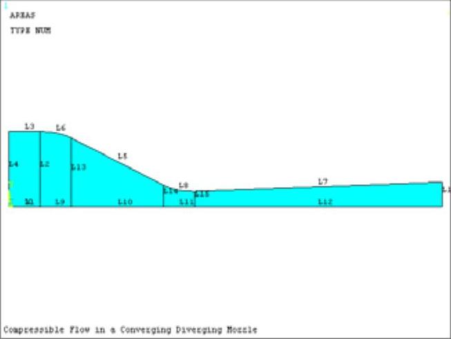
图6-10 生成的几何模型
注意
每输入一个单击一次“Apply”按钮。(https://www.xing528.com)
 单击“Close”按钮关闭该对话框。
 依次选择Main Menu→Preprocessor→Meshing→Size Cntrls→ManualSize→Lines→Picked Lines,会弹出“Element Sizes on Picked Lines”对话框,用鼠标拾取线段4。
 单击“Apply”按钮,会弹出“Element Sizes on Picked Lines”对话框,如图6-12所示,在“NDIVNo.of element divisions”输入框中输入“ntran”,在“SPACE Spacing ratio”输入框中输入“rtran”。
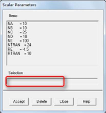
图6-11 “Scalar Parameters”对话框
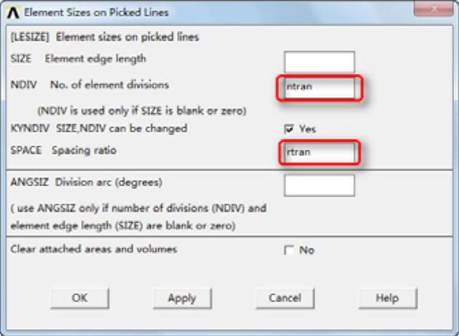
图6-12 “Element Sizes on Picked Lines”对话框
 单击“Apply”按钮,会再次弹出“Element Sizes on Picked Lines”对话框,用鼠标拾取线段2。
 单击“Apply”按钮,会再次弹出“Element Sizes on Picked Lines”对话框,如图6-12所示,在“NDIVNo.of element divisions”输入框中输入“ntran”,在“SPACE Spacing ratio”输入框中输入“rtran”。
 单击“Apply”按钮,会再次弹出“Element Sizes on Picked Lines”对话框,用鼠标拾取线段13。
 单击“Apply”按钮,会再次弹出“Element Sizes on Picked Lines”对话框,如图6-12所示,在“NDIVNo.of element divisions”输入框中输入“ntran”,在“SPACE Spacing ratio”输入框中输入“1/rtran”。
 单击“Apply”按钮,会再次弹出“Element Sizes on Picked Lines”对话框,用鼠标拾取线段14。
 单击“Apply”按钮,会再次弹出“Element Sizes on Picked Lines”对话框,如图6-12所示,在“NDIVNo.of element divisions”输入框中输入ntran,在“SPACE Spacing ratio”输入框中输入1/rtran。
 单击“Apply”按钮,会再次弹出“Element Sizes on Picked Lines”对话框,用鼠标拾取线段15。
 单击“Apply”按钮,会再次弹出“Element Sizes on Picked Lines”对话框,如图6-12所示,在“NDIVNo.of element divisions”输入框中输入“ntran”,在“SPACE Spacing ratio”输入框中输入“1/rtran”。
 单击“Apply”按钮,会再次弹出“Element Sizes on Picked Lines”对话框,用鼠标拾取线段16。
 单击“Apply”按钮,会再次弹出“Element Sizes on Picked Lines”对话框,如图6-12所示,在“NDIVNo.of element divisions”输入框中输入“ntran,”在“SPACE Spacing ratio”输入框中输入“1/rtran”。
 单击“Apply”按钮,会再次弹出“Element Sizes on Picked Lines”对话框,用鼠标拾取线段1。
 单击“Apply”按钮,会再次弹出“Element Sizes on Picked Lines”对话框,如图6-12所示,在“NDIVNo.of element divisions”输入框中输入“na”,在“SPACE Spacing ratio”输入框中输入1。
 单击“Apply”按钮,会再次弹出“Element Sizes on Picked Lines”对话框,用鼠标拾取线段3。
 单击“Apply”按钮,会再次弹出“Element Sizes on Picked Lines”对话框,如图6-12所示,在“NDIVNo.of element divisions”输入框中输入na,在“SPACE Spacing ratio”输入框中输入1。
 单击“Apply”按钮,会再次弹出“Element Sizes on Picked Lines”对话框,用鼠标拾取线段6。
 单击“Apply”按钮,会再次弹出“Element Sizes on Picked Lines”对话框,如图6-12所示,在“NDIVNo.of element divisions”输入框中输入nb,在“SPACE Spacing ratio”输入框中输入1。
 单击“Apply”按钮,会再次弹出“Element Sizes on Picked Lines”对话框,用鼠标拾取线段9。
 单击“Apply”按钮,会再次弹出“Element Sizes on Picked Lines”对话框,如图6-12所示,在“NDIVNo.of element divisions”输入框中输入nb,在“SPACE Spacing ratio”输入框中输入1。
 单击“Apply”按钮,会再次弹出“Element Sizes on Picked Lines”对话框,用鼠标拾取线段5。
 单击“Apply”按钮,会再次弹出“Element Sizes on Picked Lines”对话框,如图6-12所示,在“NDIVNo.of element divisions”输入框中输入nc,在“SPACE Spacing ratio”输入框中输入1。
 单击“Apply”按钮,会再次弹出“Element Sizes on Picked Lines”对话框,用鼠标拾取线段10。
 单击“Apply”按钮,会再次弹出“Element Sizes on Picked Lines”对话框,如图6-12所示,在“NDIVNo.of element divisions”输入框中输入nc,在“SPACE Spacing ratio”输入框中输入1。
 单击“Apply”按钮,会再次弹出“Element Sizes on Picked Lines”对话框,用鼠标拾取线段8。
 单击“Apply”按钮,会再次弹出“Element Sizes on Picked Lines”对话框,如图6-12所示,在“NDIVNo.of element divisions”输入框中输入nd,在“SPACE Spacing ratio”输入框中输入1。
 单击“Apply”按钮,会再次弹出“Element Sizes on Picked Lines”对话框,用鼠标拾取线段11。
 单击“Apply”按钮,会再次弹出“Element Sizes on Picked Lines”对话框,如图6-12所示,在“NDIVNo.of element divisions”输入框中输入nd,在“SPACE Spacing ratio”输入框中输入1。
 单击“Apply”按钮,会再次弹出“Element Sizes on Picked Lines”对话框,用鼠标拾取线段7。
 单击“Apply”按钮,会再次弹出“Element Sizes on Picked Lines”对话框,如图6-12所示,在“NDIVNo.of element divisions”输入框中输入ne,在“SPACE Spacing ratio”输入框中输入re。
 单击“Apply”按钮,会再次弹出“Element Sizes on Picked Lines”对话框,用鼠标拾取线段12。
 单击“Apply”按钮,会再次弹出“Element Sizes on Picked Lines”对话框,如图6-12所示,在“NDIVNo.of element divisions”输入框中输入ne,在“SPACE Spacing ratio”输入框中输入re,单击“OK”按钮关闭该对话框。
 依次选择Main Menu→Preprocessor→Meshing→Mesh→Areas→Mapped→3 or 4 sided,会弹出“Mesh Areas”对话框,单击“Pick All”按钮,生成的网格模型如图6-13所示。
 定义边界条件。
 依次选择Utility Menu→Select→Everything。
 依次选择Main Menu→Preprocessor→Numbering Ctrls→Compress Numbers,会弹出“Compress Numbers”对话框,如图6-14所示,在“Label Item to be compressed”后的下拉框中选择“Nodes”。
 单击“Apply”按钮,再次弹出“Compress Numbers”对话框,在“Label Item to be compressed”后的下拉框中选择“Elements”,单击“OK”按钮关闭该对话框。
 依次选择Utility Menu→Plot→Lines。
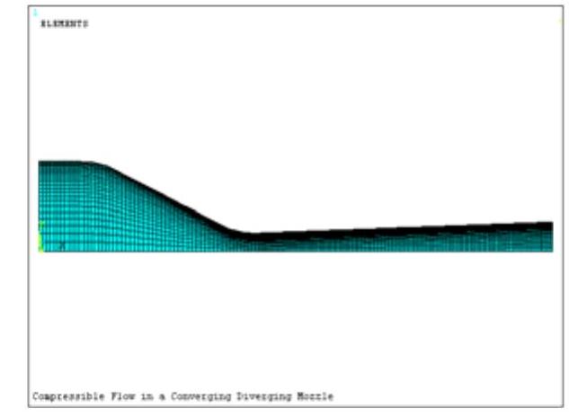
图6-13 生成的网格模型
 依次选择Utility Menu→Select→Entities,会弹出“Select Entities”对话框,在第一个下拉框中选择“Lines”,在第二个下拉框中选择“ByNum/Pick”,在第三个单选框中选择“From Full”,如图6-15所示。单击“OK”按钮,会弹出“Select Lines”对话框,用鼠标选择线段L1、L9、L10、L11、L12,单击“OK”按钮关闭对话框。
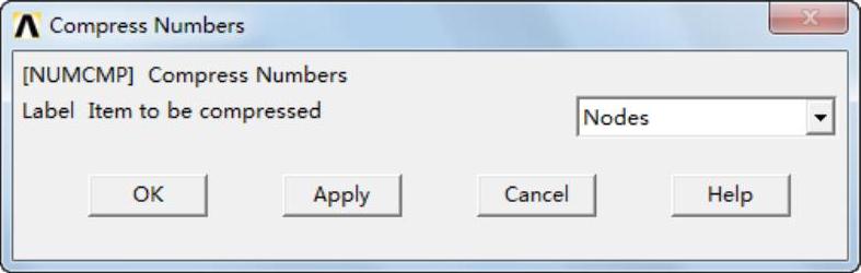
图6-14 “Compress Numbers”对话框
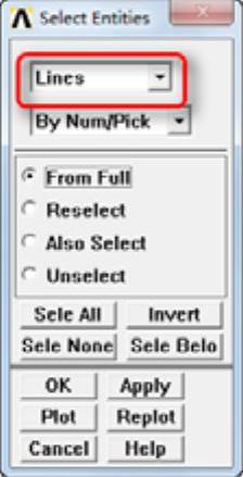
图6-15 “Select Entities”对话框
 依次选择Utility Menu→Select→Entities,会弹出“Select Entities”对话框。在第一个下拉框中选择“Nodes”,在第二个下拉框中选择“Attached to”,在第三个单选框中选择“Lines,all”,如图6-16所示。单击“OK”按钮关闭该对话框。
 依次选择Main Menu→Preprocessor→Loads→Define Loads→Apply→Fluid/CFD→Velocity→On Nodes,会弹出“ApplyVonNodes”对话框。单击“PickAll”按钮,会弹出“Apply VELO load on nodes”对话框,如图6-17所示。
 在“Apply VELO load on nodes”对话框中,在“VY a Load value”输入框中输入0,如图6-17所示,单击“OK”按钮关闭该对话框。
 依次选择Utility Menu→Select→Entities,会弹出“Select Entities”对话框,在第一个下拉框中选择“Lines”,在第二个下拉框中选择“ByNum/Pick”,在第三个单选框中选择“FromFull”,如图6-15所示。单击“OK”按钮,会弹出“Select Lines”对话框,用鼠标选择线段L4,单击“OK”按钮关闭对话框。
 依次选择Utility Menu→Select→Entities,会弹出“Select Entities”对话框。在第一个下拉框中选择“Nodes”,在第二个下拉框中选择“Attachedto”,在第三个单选框中选择“Lines,all”,如图6-16所示。单击“OK”按钮关闭该对话框。
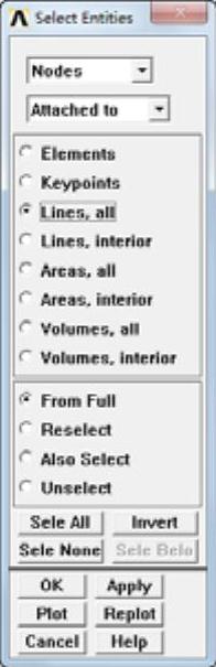
图6-16 “Select Entities”对话框
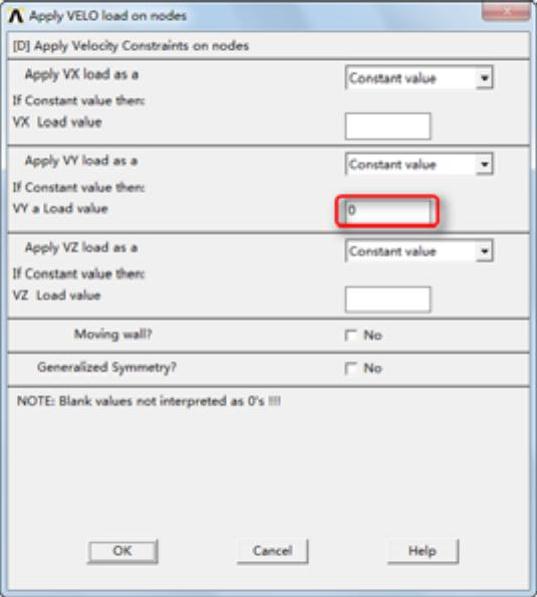
图6-17 “Apply VELO load on nodes”对话框
 依次选择Main Menu→Preprocessor→Loads→Define Loads→Apply→Fluid/CFD→Pressure DOF→On Nodes,会弹出“Apply PRES on nodes”对话框,如图6-18所示。
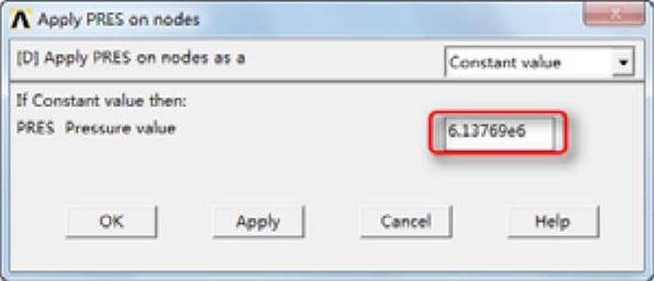
图6-18 “Apply PRES on nodes”对话框
 在“Apply PRES on nodes”对话框中,在“PRES Pressure value”输入框中输入6.13769e6,如图6-18所示,单击“OK”按钮关闭该对话框。
 依次选择Utility Menu→Select→Entities,会弹出“Select Entities”对话框,在第一个下拉框中选择“Lines”,在第二个下拉框中选择“By Num/Pick”,在第三个单选框中选择“From Full”,如图6-15所示。单击“OK”按钮,会弹出“Select Lines”对话框,用鼠标选择线段L3、L5、L6、L7、L8,单击“OK”按钮关闭对话框。
 依次选择Utility Menu→Select→Entities,会弹出“Select Entities”对话框。在第一个下拉框中选择“Nodes”,在第二个下拉框中选择“Attached to”,在第三个单选框中选择“Lines,all”,如图6-16所示。单击“OK”按钮关闭该对话框。
 依次选择Main Menu→Preprocessor→Loads→Define Loads→Apply→Fluid/CFD→Velocity→On Nodes,会弹出“Apply Von Nodes”对话框。单击“Pick All”按钮,会弹出“Apply VELO load on nodes”对话框,如图6-17所示。
 在“Apply VELO load on nodes”对话框中,在“VX a Load value”输入框中输入0,在“VY a Load value”输入框中输入0,单击“OK”按钮关闭该对话框。
 依次选择Utility Menu→Select→Entities,会弹出“Select Entities”对话框,在第一个下拉框中选择“Lines”,在第二个下拉框中选择“ByNum/Pick”,在第三个单选框中选择“From Full”,如图6-15所示。单击“OK”按钮,会弹出“Select Lines”对话框,用鼠标选择线段L16,单击“OK”按钮关闭对话框。
 依次选择Utility Menu→Select→Entities,会弹出“Select Entities”对话框。在第一个下拉框中选择“Nodes”,在第二个下拉框中选择“Attached to”,在第三个单选框中选择“Lines,all”,如图6-16所示。单击“OK”按钮关闭该对话框。
 依次选择Main Menu→Preprocessor→Loads→Define Loads→Apply→Fluid/CFD→Pressure DOF→On Nodes,会弹出“Apply PRES on Nodes”对话框,如图6-18所示。
 “Apply PRES on nodes”对话框中,在“PRES Pressurevalue”输入框中输入0,单击“OK”按钮关闭该对话框。施加边界条件后的模型如图6-19所示。
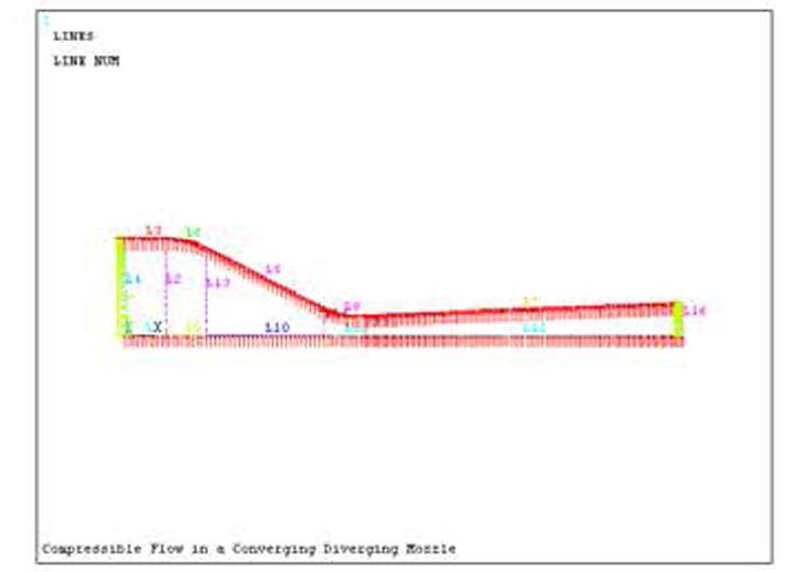
图6-19 施加载荷后的模型
免责声明:以上内容源自网络,版权归原作者所有,如有侵犯您的原创版权请告知,我们将尽快删除相关内容。