


Step1.在特征树中选择“Point to Point.1(Computed)”节点,然后选择下拉菜单 命令,插入一个轮廓铣削加工操作,系统弹出“Profile Contouring.3”对话框(一)。
Step2.定义几何参数。
(1)进入几何参数选项卡。在“Profile Contouring.3”对话框中单击 选项卡。
选项卡。
(2)选择轮廓铣削类型。在“Profile Contouring.3”对话框的 下拉列表中选择
 选项。
选项。
(3)定义加工区域。单击“Profile Contouring.3”对话框中的侧面轮廓感应区,在图形区选择图19.60所示的轮廓线,在图形区空白处双击鼠标左键,系统返回到“Profile Contouring.3”对话框;单击“Profile Contouring.3”对话框中的顶面感应区,在图形区选择图19.60所示的模型平面,系统返回到“Profile Contouring.3”对话框;单击“Profile Contouring.3”对话框中的底面感应区,在图形区选择图19.60所示的模型平面,系统返回到“Profile Contouring.3”对话框。
说明:如果轮廓线上的箭头指向不正确,可以通过单击该箭头进行调整。
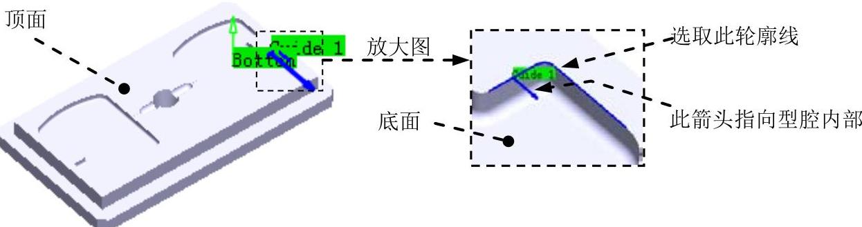
图19.60 定义侧面轮廓和底面
Step3.定义刀具参数。
(1)进入“刀具参数”选项卡。在“Profile Contouring.3”对话框中单击“刀具参数”选项卡 。
。
(2)选择刀具类型。在“Profile Contouring.3”对话框中单击 按钮,选择端铣刀为加工刀具。
(3)刀具命名。在 文本框中输入“T8 End Mill D 2”并按下Enter键。
(4)设置刀具参数。在“Profile Contouring.3”对话框中选中 复选框,单击
 按钮,在
按钮,在 选项卡中设置图19.61所示的刀具参数。
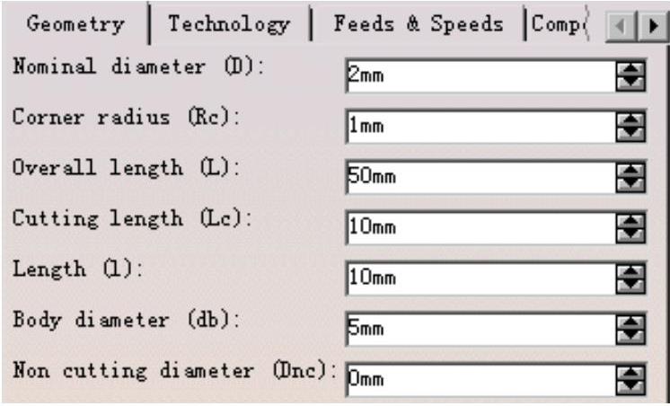
图19.61 定义刀具参数
Step4.定义进给率。
(1)进入“进给率”选项卡。在“Profile Contouring.3”对话框中单击 选项卡。
选项卡。
(2)设置进给率。在“Profile Contouring.3”对话框的 选项卡中设置图19.62所示的参数。
Step5.设置刀具路径参数。(https://www.xing528.com)
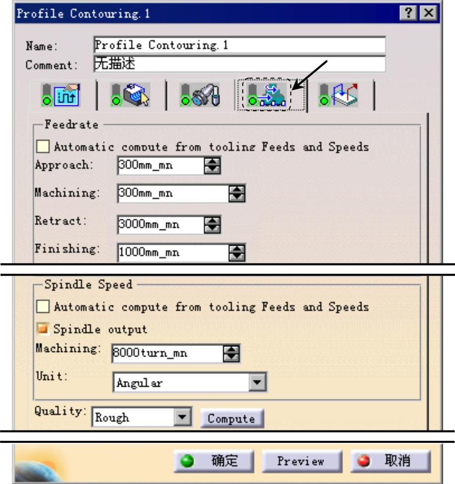
图19.62 “进给率”选项卡
(1)进入“刀具路径参数”选项卡。在“Profile Contouring.3”对话框中单击 选项卡。
选项卡。
(2)定义刀具路径类型。在“Profile Contouring.3”对话框的 下拉列表中选择
 选项。
选项。
(3)定义切削参数。单击 选项卡,采用系统默认的参数设置值。
(4)定义进给参数。单击 选项卡,设置图19.63所示的参数。
(5)定义精加工参数。单击 选项卡,设置图19.64所示的参数。
(6)其他选项卡中的参数采用系统默认设置值。
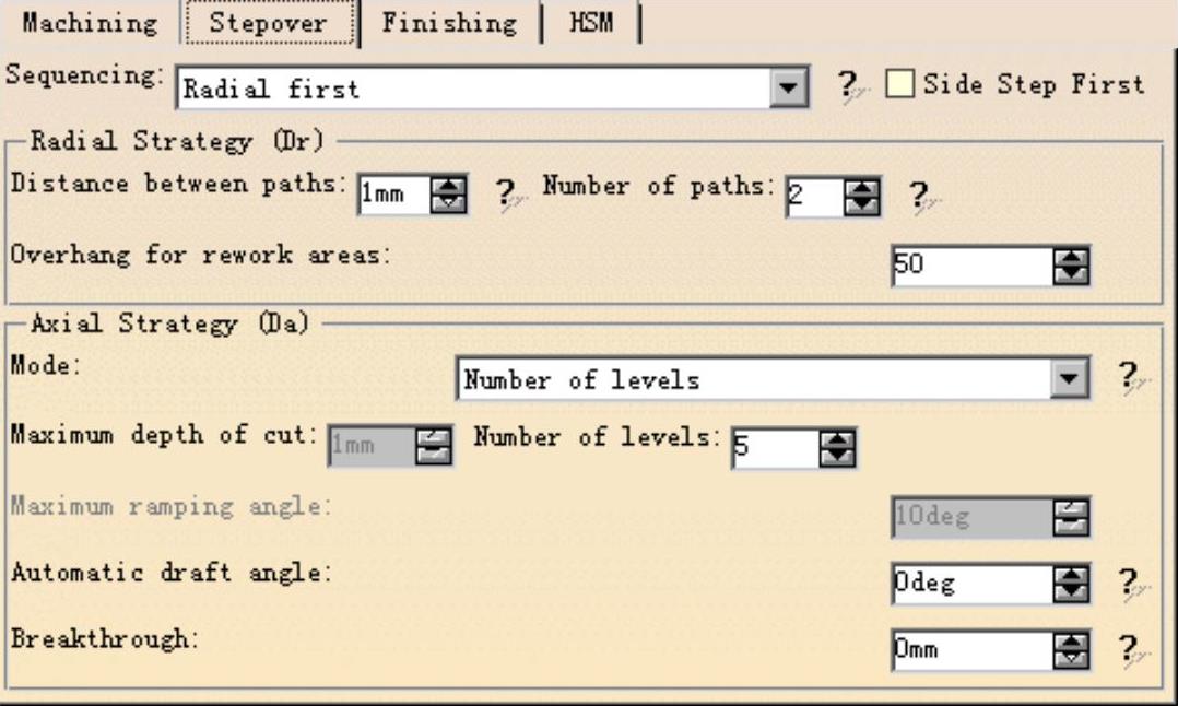
图19.63 定义进给参数
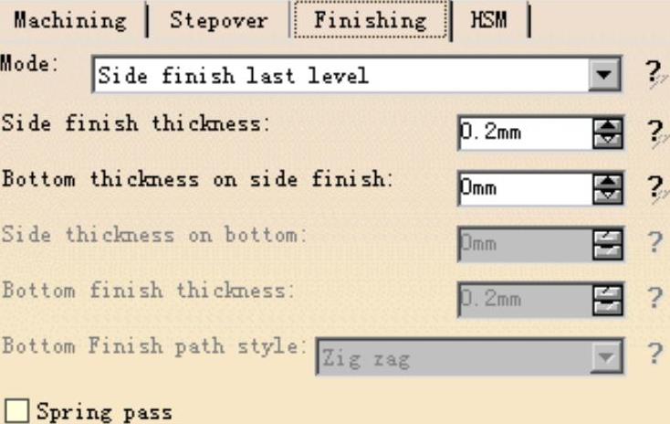
图19.64 定义精加工参数
Step6.定义进刀/退刀路径。采用系统默认的参数设置值。
Step7.刀路仿真。
(1)在“Profile Contouring.3”对话框(一)中单击“Tool Path Replay”按钮 ,系统弹出“Profile Contouring.3”对话框(二),且在图形区显示刀路轨迹(图19.65)。
(2)在“Profile Contouring.3”对话框(二)中单击 按钮,然后单击“Profile Contouring.3”对话框(一)中的
 按钮。
按钮。

图19.65 显示刀路轨迹
免责声明:以上内容源自网络,版权归原作者所有,如有侵犯您的原创版权请告知,我们将尽快删除相关内容。